
In the past, entry-level audio interfaces were sufficient to measure the THD+N of amplifiers (as long as you dropped the voltage appropriately to match the input range). However, recent improvements in "chip amp" performance have made it possible for the DIYers to build amplifiers that exceed SINAD 100. So there is a desire to measure amplifiers with high performance ADCs like the Cosmos ADC. The Cosmos ADC has a tiny 2.5mm 43Vrms AUX input for measuring amps, and it is easy to measure a traditional Class AB amplifier. Let us start with the measurement of a Class-AB amplifier. On the other hand, measuring Class-D amplifiers is difficult. How to measure Class D amplifiers with Cosmos ADC will be explained in the second half of this blog.
Intended audience: Anyone who has measured DACs with Cosmos ADC and REW; basic usage of Cosmos ADC and REW will not be explained.
I. Measuring Class-AB Amplifiers
You don't want to blast out the speakers while measuring the target amplifier, so you need a dummy load to take the place of the speakers. Next, you need a measurement cable to connect an amplifier to the Cosmos ADC. You need a DAC to generate test waves. Measurement software such as ARTA or Room EQ Wizard (REW) is also required. I will use REW for this example.
1. Dummy Load

Fig.1: Dummy Load 8Ω and 4Ω
These are my dummy loads. The left one is made up of four 2Ω 50W metal-clad resistors in series which can be used as an 8Ω dummy load up to 200W, or a 4Ω dummy load up to 100W if you use the middle jack.
Because 100W was not enough for some of my amps, I made the second one (right one) with 1Ω 50W metal-clad resistors. It can be used as a 4Ω dummy load up to 200W.
2. Measurement Cable
Soldering wires to a tiny 2.5mm plug was difficult for me. Therefore, I cut a cable with 2.5mm plugs and soldered alligator clips on one side. (Fig.2) The plastic housing of the 2.5mm plug was shaved off because it interfered with the screw and LED of the Cosmos ADC. (Fig.3)

Fig.2: Measurement Cable

Fig.3: Shaved plastic housing
3. DAC
The SINAD of your DAC must be at least 10 dB higher than the SINAD of the amplifier you are measuring. If you want to measure THD+N vs Level, the DAC's SINAD must be higher than the amp's not only at Full Scale (0dBFS) but at all levels. For example, TOPPING D50 (not D50s, the older one) has the infamous "IMD Hump" in mid-level. This affects not only IMD but also THD, and therefore THD+N (Fig.4). And it also affects the amplifier's THD+N vs level measurements (Fig.5). To confirm that your DAC does not have such a distortion hump, check the IMD (Intermodulation Distortion) vs Level measurement at ASR. For example, TOPPING D30Pro does not have the IMD hump.

Fig.4: THD+N vs Level. TOPPING D50 (red) and D30Pro (green)
Note: Y-axis values (dBr) are incorrect. I used the 1kHz notch of the Cosmos APU for this measurement but for some reason REW did not use the cal file in the stepped sine measurement. So dBr values of the Y-axis are 30dB worse than real.

Fig.5: THD vs DAC Level. Amplifier (red) and D50 DAC (green)
The distortion of the TOPPING D50 DAC pushes up the distortion of the amplifier at the mid level.
4. Connecting Instruments for Class AB Amplifier Measurement

Fig.6 Connecting PC, DAC, Cosmos ADC, the target amplifier and the dummy load.
To measure L channel of the amplifier,
- Connect the USB DAC and the Cosmos ADC to your PC or Mac.
- Connect LINE OUT L-ch of your USB DAC to LINE IN L-ch of the target amplifier. Do NOT connect R-ch cable.
- LINE IN R-ch of the amplifier can be open, but it is better to short-circut the jack. (Short-circut the signal and GND pins of the LINE IN R-ch jack.)
- Connect Speaker OUT L-ch to the dummy load. Speaker OUT R-ch can be open. Use short and thick speaker wire cables so that you can ignore the resistance of the wire.
- Connect the L+ and L- clips of the Cosmos ADC measurement cable to the amp's speaker terminals (or speaker wires). Or, if you ignore the resistance of the speaker wires, you may connect to the dummy load terminals instead of the amp's speaker terminals.

Fig.7: Amp, USB DAC, Dummy Load, Cosmos ADC and Mac.

Fig.8: Enlarged view around the speaker terminals

Fig 9: RCA plug to short LINE IN R-ch jack.
EDIT: Driving only one channel improves SINAD by several dB and increases maximum output, that is not accurate for Stereo Amplifier Measurement. Please refer to the following note at the end of this page.
EDIT: June 6th, 2023
EDIT: November 12, 2025
5. Calibration in REW
With the amplifier, DAC, dummy load, Cosmos ADC and PC connected, let's set voltage. Launch RTA from the REW main window. Then, enter 43 into the "FS sine Vrms" field of the RTA. If you trust the calibration by E1DA at the shipment (I do trust), that's it.
EDIT: The input range for the AUX 2.5 mm jack correlates with the DIP switch for the XLR input range. Set the DIP switch to 10 Vrms to set the AUX input range to 43 Vrms.
Or, if you have an accurate DVM, DMM or oscilloscope, you can calibrate the input level.
- Launch Generator and RTA from the main REW window.
- Set the volume of the amplifier to what you would normally hear (or adjust Generator's dBFS for a pure power-amp).
- Generate a 1kHz (or 997Hz if you like) sine signal and send it to the DAC.
- Start the RTA.
- Click the "Calibrate level" button.
- Measure the actual voltage at the speaker terminals of the amp.
- Enter the voltage (Vrms) into the "Calibrate Level" dialog box and click the Calibrate button. (Fig.10)

Fig.10 Calibrating Input Level

Fig.11 Setting dummy load registance
REW can convert voltage to power (W or dBW) by entering the resistance of the dummy load. Enter 8 for the 8Ω dummy load (and 4 for 4Ω) in the Appearance dialog box.
The tolerance for metal-clad resistors is not high. Mine is +/- 5%. If you have an accurate DMM, you can mesure the accutual resistance of the dummy load including speaker wire cable. Mine are 7.9Ω and 4.0Ω without cable, 8.0Ω and 4.1Ω with the cable.
6. Measuring THD+N

Fig.12 Distortion and noise of DENON PMA-800NE

Fig 13. REW Stepped Measurement
Now all set. Let us measure the THD+N of the amplifier with RTA. Amplifier THD+N is usually compared at 5W. You can set Y axis of the RTA to W (wats), and ajusting the volume knob of the amp and/or Generator dBFS, set the power to 5W. If your dummy load is 8Ω, voltage will be SQRT(5W x 8Ohm) = 6.3V.
THD+N of DENON PMA-800NE at 5W 8Ohm is -82.1dB or 0.008%. (Fig.12)
REW RTA has the Stepped Measurement function. You can use this function to measure THD vs frequency, THD vs level, IMD vs level and Multitone TD+N vs level. Refer to REW Help for details.
To measure THD+N vs level,
- Click the "Stepped sine" button in the RTA. (Fig.13)
- Set the 'Test' field to "THD vs Level".
- Set other fields as needed.
- Turn the amplifier volume to maximum
- Click the Start button.
When the stepped measurement is completed, the results are displayed in the REW main window, not in the RTA window. (Fig.14)
You can use the Overlays button to display multiple results. For example, display L-ch and R-ch results, 4Ω and 8Ω results, etc. (Fig.15: THD+N vs Level of DENON PMA-800NE, 4Ω and 8Ω.)

Fig.14 Results in the REW main window

Fig.15 THD+N vs Level of DENON PMA-800NE
The nominal specification of the DENON PMA-800NE is THD="0.01% (-80dB) at Rated output (50W) –3 dB, 8Ω, 1 kHz". The measured results were somewhat better than the nominal specs.
II. Measuring Class-D amplifiers
7. Issues in Measuring Class-D Amplifiers
Measuring a Class-D amplifier or switching amplifier is not as easy as measuring a Class-AB amplifier. The first issue is that (not all but) many Class-D amplifiers today adopt Bridge Tied Load (BTL) to produce more power. These amplifiers share the negative (-) speaker terminal and GND. For this reason, connecting a DAC and an ADC to a PC for measurement may cause noise or, in the worst case, shutdown (or damage) the amplifier. USB isolator (like TOPPING HS02) may solve this issue. Fortunately, a BTL amplifier worked with the 2.5mm jack of the Cosmos ADC.
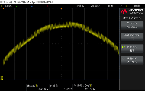
Fig.16 PWM signal noise in audio signal
The second issue is pulse-width modulation (PWM) signal noise. The output of a Class-D amplifier contains a high-frequency (typically between 250kHz and 600kHz) sine wave. This is a leakage of the PWM carrier wave. (Fig.16)
Such a high-frequency signal is not a problem for real loudspeakers at all. But it does affect the amplifier measurement. Please see Video.1. This is the FFT (REW RTA result) of the Aiyima A07, a Class-D amplifier. As you can see, THD does not change much, but N varies between 300μV and 1.4mV and becomes unstable. As a result, THD+N varies between -73dB and -88dB. So, I could not accurately measure the THD+N of the Class-D amplifier.
Video.1 Aiyima A07 FFT (Cosmos ADC 2.5mm AUX)

Fig.17 Aiyima A07 THD+N vs Level (Cosmos ADC 2.5mm AUX)
Fig. 17 shows the THD+N vs Level of the Aiyima A07 class-D amplifier, measured in the same way as before (6. Measuring THD+N). Two measurements were taken, and it can be seen that there are considerable differences between the two measurements.
Audio Precision sells switching amplifier measurement filters that remove high-frequency PWM signal noise. However, these filters require an ADC input impedance of at least 100kΩ, so they cannot be used with the lower impedance Cosmos ADC.
8. Low Pass Filter (LPF)

Fig.18 LPF Schematics

Fig.19 LPF BOM
I consulted my friend Y. Goto-san, who is a professional electronic circuit designer. He designed a passive RC low pass filter (LPF) for me. He told me that the unbalanced input (Cosmos ADC AUX 2.5mm jack) was difficult to work with BTL amplifiers. So we have decided to use the balanced (XLR) input of the Cosmos ADC (setting 10Vrms input range) instead of the 43Vrms 2.5mm jack.
The LPF has two stages - R1/C1 and R2/C2. Each fc is 24kHz so that it can cut high frequency and does not afect <20kHz much.
R3 is for level adjustment. The series composite resistance of LPF is 506Ω (33Ωx2 + 220Ωx2). If you use 160Ω for R3, Cosmos ADC input impedance 3.48kΩ and 160Ω in parallel = 153Ω. The voltage drop ratio = 153/(506+153) = 0.2322. 10Vrms/0.2322 = input range 43Vrms.
I did not have a 160Ω resistor, so I used 560Ω in parallel (280Ω). So the same calculation gives my input range = 29.5Vrms, capable to measure up to 109W with 8Ω load or 218W with 4Ω.

Fig.20 LPF and measurement cable for Cosmos ADC

Fig.21 LPF connected between amplifier and Cosmos ADC
9. Testing the DIY LPF
You can enter the calculated input range (29.5Vrms in may case) into the "FS sine Vrms" field of the RTA. Or, if you have an accurate DVM, DMM or oscilloscope, you can calibrate the input level. (5. Calibration in REW). As a third method, I used the following approach.
- Setup PC, DAC, amp, dummy load and Cosmos ADC as "6. Measuring THD+N" (same method as Class-AB amp measurement.)
- Generate and send 1kHz signal to DAC/amp, and read the voltage with REW RTA.
- Setup PC, DAC, amp, dummy load and Cosmos ADC with the LPF (as "8. Low Pass Filter (LPF)")
- Generate the same level of the 1kHz signal and send it to DAC/amp
- Click on the "Calibrate level" button of REW RTA and enter the voltage without LPF (the voltage read at step 2.)
See Video.2, FFT (REW RTA) with the LPF. Compared with Video.1, the THD of Video.2 (-99dB) is almost the same as that of Video.1 (-98dB). While N (190μV) and THD+N (89.9dB) are now stable.
Again, 2 measurements of THD+N vs. Level were made, each with and without the LPF. The LPF did not have much effect on the THD, but made the noise (N) much more stable. As with the Class AB amplifier, the lines of the two measurements taken overlap. (Fig.22) Apparently, my LPF works well with the Class-D amp.
Video.2 Aiyima A07 FFT with LPF

Fig.22 THD+N vs Level with / without LPF
10. Measuring Aiyima A07
I found a review and measurements of Aiyima A07 at the Audio Science Review (ASR) site. So I can compare my measurement with Amir's accurate measurement using Audio Precision (AP) and check if my measurement is accurate too. In the ASR measurement there is a mains leakage at 60 Hz, but in my measurement there is not such a large leakage. I used the 32V/5A AC adapter that comes with the Aiyima A07, so it shoud be same as the FFT measurement in the ASR site. I did not observe the mains leakage even without LPF, so I do not know the cause of the difference. SINAD comparisons are as follows:
SINAD ASR measurement: Ch-1 82.053dB / Ch-2 83.323dB
SINAD My measurement: L 86.7dB / R 87.0dB
SINAD at 5W into 4Ω is better in my measurement than in Amir's. Again, I do not know the reason for this difference. Maybe because of the noise level including the mains leakage? I hope the LPF did not remove the noise, but I am not sure.
Then, let us compare power vs distortion:
Max Power ASR measurement: 77W@4Ω / 48W@8Ω
Max Power My measurement: 84W@4Ω / 44W@8Ω
There are also some differences at the max power. One possible reason for this is that both channels were driven in the ASR measurement, while only one channel was driven in my measurement. Therefore, Aiyima A07 might shutdown at 77W@4W in the ASR measurement. SINAD at maximum output is also slightly better in my measurement than in ASR's.

Fig.23 Aiyima A07 4Ω 5W FFT

Fig24. Aiyima A07 THD+N vs Level 4Ω/8Ω
My measurements did not exactly match the Amir's results. So I reserve the conclusion whether my measurement results are correct or not. It is possible that my measurement method has this degree of error (SINAD 82dB vs. 87dB).
Acknowledgement
Ivan@E1DA, thank you for reviewing this page and providing us with insightful feedback.
EDIT: June 6th, 2023
I wrote:
There are also some differences at the max power. One possible reason for this is that both channels were driven in the ASR measurement, while only one channel was driven in my measurement. Therefore, Aiyima A07 might shutdown at 77W@4W in the ASR measurement.
My measurements did not exactly match the Amir's results. So I reserve the conclusion whether my measurement results are correct or not. It is possible that my measurement method has this degree of error (SINAD 82dB vs. 87dB).
So, I drove both channels of the Aiyima A07 and measured THD+N vs Level again. As a result, I got the same values as Amir measured with the AP! Aiyima A07 shutdown at 77W. SINAD at 5W was 82dB.

EDIT: November 12, 2025
As mentioned above, amplifier measurements should drive both channels, not just one channel. Driving only one channel improves SINAD by several dB and increases maximum power, that is not accurate. Therefore, I assembled new dummy loads to enable driving both channels. I connected four 1 Ω/50 W metal-clad resistors in series to assemble a 4 Ω/200 W dummy load, and I made two of them. I also made an additional 8 Ω/200 W dummy load.
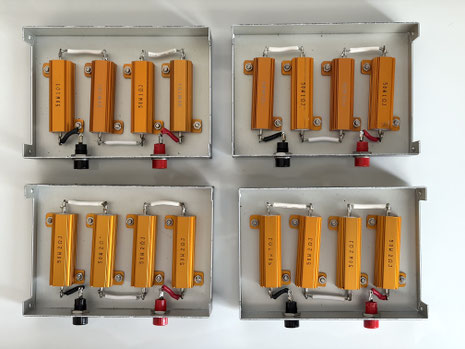
The tolerance of the metal-clad resistors that I used is quite large, at 5%. If you have a high-precision digital multimeter (DMM), it's best to measure the resistance value of each resistor and adjust the two dummy loads so their combined resistance is as close as possible.
Here's an example:
1 1.984Ω
2 1.992Ω
3 2.002Ω
4 1.991Ω
5 1.974Ω
6 2.026Ω
7 1.975Ω
8 1.974Ω
1+5+6+7 = 7.958Ω
2+3+4+8 = 7.958Ω
Last edited: November 12, 2025
